[seopress_breadcrumbs]
The Power Behind Ultrasonic Cleaning
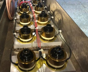
Two Ultrasonic Transducers: with the lid off (back), with the lid welded on (front)
Since all ultrasound waves are generated using the same basic technology, it follows that all ultrasonic cleaning systems include the same basic components. Energy is generated via a bank of ultrasonic transducers mounted to a radiating diaphragm (Fig. 2). This transduceris then mounted to the unit’s cleaning tank where it is immersed in water or an aqueous solution. It’s essentially a stereo system under water.
There are two types of transducers used in ultrasonic cleaning—magnetostrictive and piezoelectric. They create the same result using very different technology, therefore each has different benefits and limitations.
Magnetostrictive transducers work on the principle that iron-rich metals expand and contract when they are placed in a magnetic field. Thin plates of these metals are stacked up to make a core. Copper wire is then wrapped cylindrically around the core and the assembly is placed in a canister. When an electrical current is sent through the copper coil, a magnetic field is created and the core changes shape. When the electrical current is turned off, the coil returns to its original shape. This expansion and contraction causes the device’s canister to resonate and generate ultrasonic waves.
Magnetostrictive transducers are remarkably durable, though its overall competitive advantages are quickly decreasing as the technology around piezoelectric transducers evolves and improves. The use of iron-based metals means there is no degradation over time; metals like nickel maintain their magnetostrictive properties on a constant level for the lifetime of the ultrasonic cleaning unit. The metal stack is welded directly to the unit’s diaphragm ensuring the bond will never loosen. Also, diaphragms used with this type of transducer are usually 5 mm thick or more, eliminating the risk of cavitation erosion wear-through.
While magnetostrictive transducers have a higher mass and can drive more power into the tank, their use is limited. They can only generate a frequency between 22 and 30 kHz, so its use is restricted to cleaning applications where the parts are large, the contaminants are difficult to remove and complete removal of microscopic particles isn’t required. Their energy generation process has three steps in energy conversion—electric energy to magnetic energy to mechanical energy—making it less efficient overall.
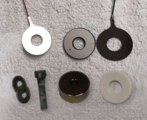
A Piezoelectric Transducer Unassembled
In piezoelectric transducers (Fig. 3), crystals with special electrical properties called lead zirconate titanate are connected with electrical wires attached to opposite faces of the crystal. Both the crystal and wires are housed between two metal plates. These layers are then stacked together and fastened down. (Fig. 4) When electricity is passed through the crystal, it changes its shape. When the electricity is taken away, it returns to its original shape. This vibration causes the unit’s diaphragm to vibrate and create the ultrasonic wave necessary for the cleaning process.
Piezoelectric transducers are less expensive to make and offer a wider variety of applications. These transducers can produce a wide variety of frequencies—between 25 and 170 kHz or more. They convert low-voltage electrical energy into mechanical energy in one step, making them cost-efficient to run frequently and for longer periods of time.
It used to be the case that the magnetostrictive transducers held a longevity advantage over its piezoelectric counterpart for two reasons: 1) When piezoelectric transducers were first developed, they used quartz crystals which lost significant power over time. Now, piezoelectric transducers use semiconductor ceramic materials that eliminate 99 percent of that strength degradation and lengthen their lifespan. 2) The adhesives available in the early days of piezoelectric transducers weren’t very strong and would degrade over time. However, adhesives developed over the years by the aircraft industry are much stronger, making the difference between welding and adhesion virtually negligible.
Putting Transducers to Work
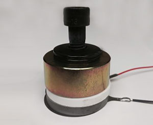
Piezoelectric Transducer Parts Assembled
When it comes to ultrasonic power generation, the frequency these transducers generate determines their effectiveness for any given application.
With lower frequencies, fewer cavitation bubbles are produced, but the bubbles are greater in both size and the energy released at implosion. This increases the likelihood of physical damage to items being cleaned. Softer metals like aluminum and brass may show what is called “cavitation burning.” Likewise, higher frequencies generate more bubbles that are smaller in size and offer a lower level of energy and gentler cleaning action.
It’s important to note that when generating an ultrasonic frequency of 25 kHz, ultrasonic units must contain a matching generator that can stand up to that mass requirement of the transducer. When frequencies between 40 and 170 kHz are required, many companies will use the same transducer along with a generator designed for the specific frequency output required for the application.
25 kHz: The Heavy Weight Boxer
A 25 kHz generator is used with larger mass items, such has a large cast iron block used for injection molding, a massive steel cutting tool or large stainless steel plates. It works best when the contaminant is on the surface of the item and requires a little more punch to remove it. This frequency also works well for removing baked on materials and is often found on plating lines for pre-treatment prior to the plating process. Larger tanks often are retrofitted with 25 kHz systems for these types of jobs.
40 kHz: The Workhorse
The vast majority of ultrasonic cleaning applications require the mid-sized cavitation bubbles created by a 40 kHz generator. Approximately 90 percent of all ultrasonic cleaning applications can be addressed at this frequency. It has enough power to shake contaminants loose but is small enough to penetrate closer to the substrate. This frequency works best when items have many through-holes and/or complicated blind holes that are difficult to reach using the larger cavitation bubbles generated at lower frequencies.
Typical applications of 40 kHz generators include carburetor cleaning, removing oils and metal chips from general machine shop applications, soot removal from items damaged in fires, cleaning of ceramics used in the high technology fields, removal of biological contaminants from surgical tools and many more.
68/132/170 kHz: The Gentle Touch
Higher frequency generators are more rare, only accounting for approximately 5 percent of the ultrasonic cleaning market. These generators offer ultra-fine gentle cleaning, including removal of micron and submicron particles, and cleaning applications that require cavitation bubbles to implode closer to the substrates being cleaned. Common applications are found in the medical and optical industries, but also in semiconductor wafer fabrication, production electronics, fine instrumentation and computer memory components.
1,000 kHz (1 MHz): Megasonics
When using frequencies of 1 MHz (1 million cycles per second) or higher, ultrasonic technology becomes megasonic technology. The energy is created using the same type of generator, just at a much higher frequency. The resulting cavitation is gentler and more controlled; only the side of the part facing the cleaning unit’s transducer is affected. This reduces or eliminates cavitation erosion and the risk of surface damage to the item being cleaned. Megasonic generators can be used when cleaning semiconductor wafers and industrial parts, but most frequently they are used when preparing silicon medical implants.
Analog vs. Digital Generators
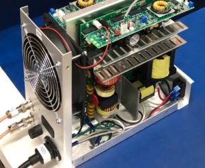
Side of Exposed Internal Ultrasonic Generator Unit
It’s important to note that all ultrasonic generators (Fig. 5) are generally analog in design. In a typical unit, all or most of its components are analog, including resistors, capacitors, transformers and inductors. The nature of the technology allows a more simple mechanical design and the use of digital technology does not enhance the effectiveness of the ultrasonic cleaning process.
Digital technology becomes useful to consider regarding circuitry and manufacturing—the machine’s controls and communications. While manual controls are still common and effective on ultrasonic units, microprocessing chips can be installed and programmed to control all or part of the machine’s adjustable levels, including frequency, frequency sweep modulation and waveform patterns.
